In the intricate world of electronics, answering the question “what does a voltage divider do?” leads us to an understanding of an essential circuit component. A voltage divider is an indispensable circuit that plays a crucial role in reducing a high voltage to a lower one by distributing voltage across resistors. Its operation is based on a straightforward principle, dividing voltage proportionally across a series of resistors, allowing different parts of a circuit to receive the voltage necessary for their optimal operation.
Introduction to Voltage Dividers
When delving into the basics, one might ask, “what is a voltage divider circuit?” Simply, it’s an arrangement within an electrical circuit that manages to split the voltage into portions using passive components like resistors. Voltage, the electromotive force propelling electrons through a conductive path, is a fundamental concept in electricity and electronics. A voltage divider, then, is comparable to a system of valves that adjusts this ‘electrical pressure’ to desirable levels for various components in an electronic circuit.
Understanding the importance of voltage division is crucial for anyone interested in the field of electronics. A critical skill is altering voltage to precise values, which affects the functionality and performance of electronic components that need specific voltage levels to operate correctly. Herein lies the significance of the voltage divider rule, which dictates how voltage is shared across resistors in a series.
At a glance, the voltage divider is comprised of a network of resistors connected in series across a voltage source. Each resistor in such a network influences the output voltage, demonstrating how ingeniously the voltage divider rule can be applied to control and manage voltage within circuits.
The Concept of Voltage Division
Digging deeper into the electrical principles behind voltage division, we find they rest firmly on established laws like Ohm’s Law and the rules for series circuits. Ohm’s Law, expressed as V = IR, highlights the relationship between voltage (V), current (I), and resistance (R). Whereas, series circuit rules note that the same current flows through each resistor, albeit voltage distribution can be different depending on individual resistances.
Resistive Voltage Divider
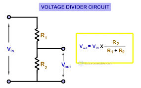
The most basic and prevalent embodiment involves the resistive voltage divider, where two or more resistors determine voltage distribution. The voltage across each resistor is calculable using the formula:
V_out = V_in * (R2 / (R1 + R2))
In this scenario, V_out signifies the output voltage across resistor R2 when V_in is the input voltage furnished by the power source. Here, R1 and R2 symbolize the resistance values of the individual resistors.
Taking practical steps on how to build a voltage divider starts by selecting and connecting resistors with known values in series. As an illustration, imagine a circuit with a 12-volt power supply (V_in) and two resistors in a series arrangement, R1 being 2kΩ and R2 being 3kΩ. Utilizing the formula, we determine the voltage across R2 (V_out) to be:
V_out = 12V * (3kΩ / (2kΩ + 3kΩ)) = 7.2V.
Through this example, we witness how to build a voltage divider and its efficacy in stepping down a supply voltage to a more manageable level for circuit components.
The Role of Load in Voltage Division
Integration of a load alters a voltage divider’s dynamic, by effectively adding another ‘resistor’ to the circuit. Ideally designed for open-circuit conditions or with a load significantly larger than the divider resistors, a considerable alteration in the load impacts the flow of current and hence the voltage distribution.
It’s imperative to acknowledge how a load might ‘load down’ the divider, drawing on its power and diminishing the voltage beneath the intended level. Such effects need to be considered during the design phase to sidestep unexpected results or potential circuit malfunctions.
Types of Voltage Dividers
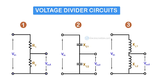
Beyond the resistive type, voltage dividers can encompass configurations using various components like capacitors and inductors. Here’s a succinct summary:
- Resistive Voltage Dividers: Harness resistors and represent the most widespread type. Suited for DC applications, they are praised for stability and predictable outputs.
- Capacitive Voltage Dividers: Utilize capacitors, these are dependent on frequency and they find their use primarily in AC circuits for tasks like reducing voltage spikes and in signal filtering functions.
- Inductive Voltage Dividers: Employ inductors and are less common due to their complex nature and the fact they’re suitable for specific applications where phase shift and inductance are factors.
| Type | Component Used | Frequency Dependency | Typical Application |
|---|---|---|---|
| Resistive | Resistors | None | DC Circuits |
| Capacitive | Capacitors | High | AC Circuits, Signal Filtering |
| Inductive | Inductors | Varies | Applications requiring phase shift adjustment |
A closer examination of these types is instrumental for selecting an appropriate voltage divider in accordance with specific circuit requirements.
Practical Applications of Voltage Dividers
Voltage dividers are not just theoretical concepts; they have widespread practical applications in the realm of electronics and circuit design. One of the primary uses of voltage dividers is in the creation of reference voltages. These reference voltages are often required in electronic circuits to set operational parameters or as comparison thresholds for integrated circuits. Therefore, understanding how to effectively implement a voltage divider is essential for creating stable and reliable electronic systems.
Sensor applications represent another area where voltage dividers prove invaluable. Many sensors output a variable resistance that depends on environmental factors, such as temperature or light. By utilizing a voltage divider, these changes in resistance can be translated into a variable voltage that can be easily read and processed by a microcontroller or an analog-to-digital converter. For example, a photoresistor in a voltage divider can be used to create a light-sensing circuit whose output voltage changes with light intensity.
Another practical application of a voltage divider is in the reduction of voltage to a safe, measurable level for instruments. When engineers need to measure high voltages, they can use a voltage divider to step down the voltage to a lower level that is within the safe measuring range of their devices. This is particularly crucial when dealing with power distribution systems where direct measurements can be hazardous.
Troubleshooting and Optimization
Even with the right setup, voltage dividers can sometimes perform poorly. Common issues with voltage dividers include inaccurate output voltages due to variations in resistor values or thermal drift, where the resistance of components changes with temperature. Additionally, the loading effect caused by a connected circuit or load can also lead to inaccuracy and inefficiency in the voltage divider’s output.
To optimize voltage divider performance, consider the following:
- Use precision resistors with tight tolerance to limit the error in voltage division.
- Factor in thermal coefficients, especially if the divider operates in varying temperature conditions, to minimize the effect of temperature on resistance.
Maintaining a voltage divider requires regular checking to ensure all connections are secure and components have not drifted significantly in value. A best practice is to occasionally measure the output voltage and compare it to expected values, recalibrating the circuit when necessary to maintain accuracy.
Another pivotal aspect of optimization is the consideration of the power rating of resistors. Resistors in a voltage divider dissipate energy in the form of heat; hence, they should have a power rating high enough to handle the power without overheating or becoming damaged.
Conclusion
To encapsulate, a voltage divider is a straightforward yet powerful tool in the toolkit of any electronics designer. Its ability to scale down voltages accurately is fundamental in the operation of complex electronic systems. From fine-tuning sensor inputs to ensuring safety when dealing with high voltages, the applications of voltage dividers are manifold and invaluable.
The voltage divider’s simplicity and effectiveness are what make it a staple in electronic circuit design — providing a time-tested solution to a variety of voltage-related challenges. It is this very flexibility and utility that underscores the continued relevance of voltage dividers in modern electronics.
FAQs
Q1: Can voltage dividers be used for both AC and DC circuits?
A1: Yes, voltage dividers can be used in both AC and DC circuits. Resistive voltage dividers are commonly used in DC circuits, while capacitive or inductive voltage dividers are used in AC circuits due to their frequency-dependent properties.
Q2: What safety precautions should be taken when using voltage dividers with high voltages?
A2: When dealing with high voltages, always ensure that the resistors can handle the power dissipated without overheating, use properly rated insulation for all components, and never touch the circuit while power is applied. It’s also recommended to work with an isolated power supply and use protective equipment.
Q3: How does the value of resistors affect the output of a voltage divider?
A3: The resistor values determine the ratio of the output voltage to the input voltage. It’s crucial to select resistors with the appropriate values and tolerance to achieve a precise output voltage.
Q4: Why is it important to consider the load when designing a voltage divider?
A4: The load directly affects the distribution of voltage and can ‘load down’ the voltage divider, resulting in a lower output voltage than designed. Including the load resistance in the design calculations is essential for accurate voltage division.
Q5: Can voltage dividers be used to power devices?
A5: Voltage dividers are not typically used as power sources because they are not designed to supply significant currents and the voltage can vary greatly with load. They are best suited for signal processing, providing reference voltages, or for measurement purposes.